GPath Laser
Camera calibration
Last updated Aug 5, 2026, 4:41 AM
1. What calibration does
An overhead camera can show the material on the bed under your design. Depending on the camera and device, it may need adjusted:
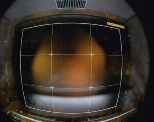
The image above has two issues:
- The view has a curved 'fisheye' effect
- The camera captures the sides of the machine, not just the bed
For the overlay to line up with the grid, GPath Laser needs two things:
| Step | Purpose |
|---|---|
| 1 · Align | Map the four corners of the work area onto the photo so shapes sit over the real bed |
| 2 · Lens | Remove fisheye bend so straight rails and sheet edges look straight |
Calibration is saved per camera (by make and model) in app settings, so it remains between projects and restarts.
2. Open the Camera tab
In the Laser operations sidebar, open the machine panel and switch to the Camera tab.
| Control | Purpose |
|---|---|
| Enable | Start (or stop) live capture from the selected device |
| Camera list | Choose which camera to use — shown by the device’s own name |
| Overlay | Show the camera on the canvas |
| Align/calibrate | Expand the calibration section with 1 · Align and 2 · Lens |
Grant camera permission in system settings if the OS prompts on first use.
3. Align the work area
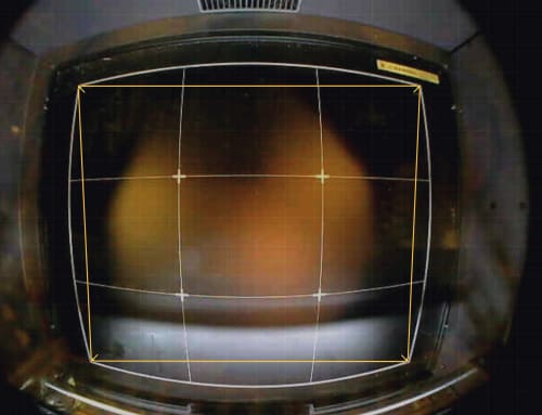
- Turn on Align/calibrate, stay on 1 · Align.
- Turn on Align work area. The camera shows its raw view and four corner arrows appear on the canvas.
- Drag each arrow onto the matching corner of the bed (or work area) as it appears in the photo.
- Zoom for precise placement — drawing tools are held off while aligning so a handle drag cannot move shapes.
- Turn Align work area off when the overlay lines up with the grid.
| Control | Purpose |
|---|---|
| Reset handles to full view | Put the arrows back on the frame corners and start again |
Align mode ends when you leave the Align step (including switching to 2 · Lens) or close the panel.
4. Straighten the lens
Wide-angle bed cameras often bend rails and sheet edges. Straighten lens solves that from edges that are straight in real life. The process involves marking which curved lines should actually be straight in real-life. This can be done manually, or auto-detect.
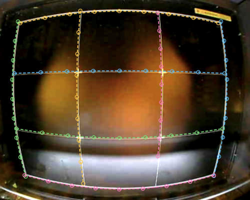
- On 2 · Lens, click Straighten lens…. A photo is taken once the wizard opens.
- Auto detect — it finds long curves typical of machine structure (bed rail, enclosure lip, sheet edge) and shows them as dashed previews. Keep these edges turns them into editable marks, or Discard to mark by hand.
- Or mark manually: click along a known straight line (3 or more points per edge), then Next edge. Edges near the sides of the frame work best.
- Click Correct to apply. The status under the button reads Lens: corrected.
- Use Fine-tune if the result is slightly over or under-corrected — left removes less bend, right removes more. The middle of the slider is the original value.
- Remove correction clears the lens fix if you need to start over.
Marking lines around the outside of the photo are more effective then in the middle.
5. Recommended order
For a new camera:
- Enable the camera and confirm the live view.
- Straighten lens first if the image is visibly bowed — alignment is more accurate on a flattened frame.
- Align work area so the four corners match the bed.
- Nudge Fine-tune if rails still look slightly curved after a first correct.
When you switch cameras, open Align/calibrate again, each device keeps its own alignment and lens correction.