GPath CNC
Finding your way around
Last updated Oct 14, 2026, 6:31 PM
1. The project workspace
The project screen is where you design, generate toolpaths, simulate, and export G-code.
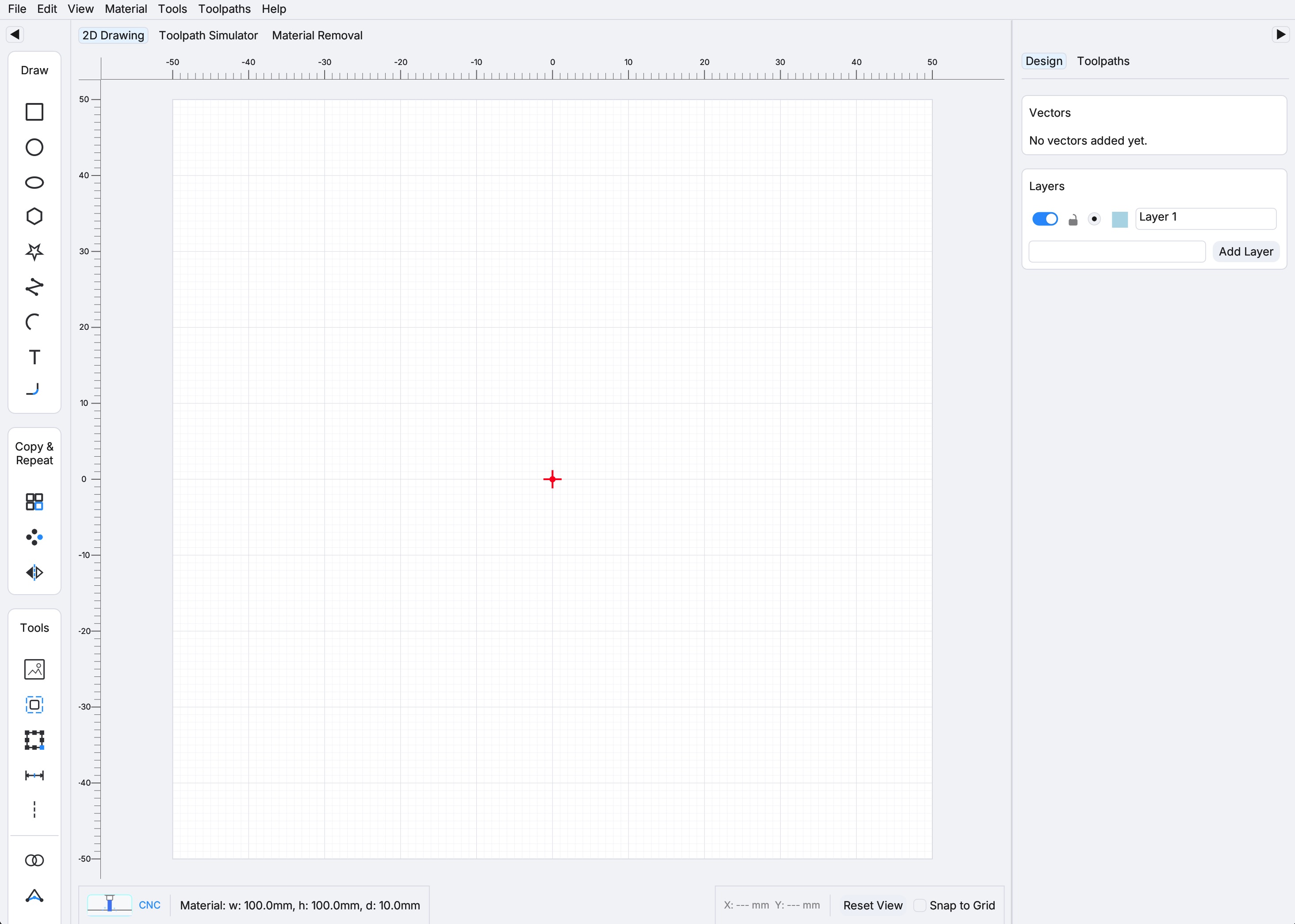
Central tabs (CNC only)
| Tab | Purpose |
|---|---|
| 2D Drawing | Primary design canvas — draw and edit shapes |
| Toolpath Simulator | Preview generated toolpath lines |
| Material Removal | View of stock as material is carved away |
Left toolbar
The left toolbar groups tools into sections:
Draw
- Square, Circle, Ellipse, Polygon, Star, Polyline, Arc, Text
Copy & Repeat
- Repeat (Grid), Repeat (Circular), Mirror
Tools
- Offset, Transform, Measure, Guideline, Boolean, Join
Selecting a tool under Draw or Copy & Repeat opens a panel on the right sidebar with various inputs (centre position, dimensions, rotation, and so on). New shapes from Draw are placed at the material centre by default. This does not apply to the Tools section — those act on the current selection or canvas rather than opening a create form.
Toggle View → Vertical left toolbar (stacked tool icons) to switch between a horizontal icon strip and a vertical stack.
Right sidebar
The right sidebar has two tabs:
| Tab | Purpose |
|---|---|
| Design | Layer list — add, rename, reorder, and toggle visibility of drawing layers |
| Toolpaths | List of generated toolpaths; create and edit profile, pocket, and drill operations |
On narrow screens the right sidebar can be collapsed. Use the toggle on the edge of the canvas to reopen it.
Bottom info bar
Shows cursor position, snap settings, reset view, and contextual status while you work.
2. Top menu bar
File
| Item | Action |
|---|---|
| New Project (⌘N / Ctrl+N) | Return to welcome screen to start fresh (prompts to save if modified) |
| Open Project… (⌘O / Ctrl+O) | Open an existing .gpath file |
| Import… | Import vector artwork (SVG, DXF, AI) onto the canvas |
| Save (⌘S / Ctrl+S) | Save the current project |
| Save As… | Save under a new filename |
| Back to Welcome Screen | Return to the welcome screen (prompts to save if modified) |
Edit
Standard editing commands: Undo, Redo, Copy, Paste, and shape deletion. See Help → Show Hotkeys for the full list.
View
Toggle canvas overlays:
- Show Center Grid
- Show Reference Point
- Show Rulers
- Show Cursor Cross
- Show Grid
- Show Toolpath Start Positions
- Show Guidelines
- Vertical left toolbar
- App theme (Dark / Light)
Material
Adjust project setup after creation:
| Item | Description |
|---|---|
| Edit Material Size | Change width, height, thickness, or unit |
| Edit Reference Point | Change the origin — existing shapes are repositioned to preserve their physical location |
| Edit Home & Safe Position | Set Home X/Y/Z (where the machine returns after a job) and Safe Z (rapid-move clearance height above the stock) |
Tools
| Item | Description |
|---|---|
| Tool Library | Manage your cutter library (diameters, feed rates, and other tool parameters used when generating toolpaths) |
Toolpaths
Create and export machining operations:
| Item | Description |
|---|---|
| New Profile Toolpath | 2D contour cut along shape edges (inside, online, and outside offsets) |
| New Pocket Toolpath | Clear material inside closed shapes |
| New Drill Toolpath | Peck or simple drilling at points |
| Save toolpaths | Export G-code (enabled once at least one toolpath exists) |
Help
- Show Hotkeys — keyboard shortcut reference
- Licence — view or manage your licence from within a project
3. Draw your first shape
With the project open on the 2D Drawing tab:
- Click Square in the left toolbar (under Draw).
- The right sidebar opens a New Square form with Position, Size, Corner Radius, and Rotation sections. Defaults are centred on the material (e.g. 50 × 50 mm for a 100 mm stock, or 2 × 2 in for a 4 in stock).
- As you edit the fields, a live preview of the square appears on the canvas.
- Click Save Changes (or press Enter) to commit the shape. It is added to the active layer and listed in the Design tab of the right sidebar.
Pan and zoom
- Scroll the mouse wheel over the canvas to zoom in and out (zoom centres on the cursor).
- Middle-mouse drag pans the view.
- The material boundary is drawn as a rectangle matching your width and height settings.
Importing files
Use File → Import… to bring in existing vector artwork (SVG, DXF, or AI). Imported paths are placed on the canvas and can be edited like hand-drawn shapes.
4. What to do next
Once you have drawings on the canvas:
- Set up your tool library — Tools → Tool Library. Add the cutters you plan to use, or use the default tools.
- Create a toolpath — Toolpaths → New Profile Toolpath (or Pocket / Drill). The right sidebar switches to the toolpath editor where you select shapes, pick a tool, and set cutting parameters.
- Simulate — Switch to the Toolpath Simulator tab to preview the cut.
- Check material removal — Switch to the Material Removal tab for a top-down view of how the stock is carved.
- Export G-code — Toolpaths → Save toolpaths once at least one toolpath has been generated.
- Save your project — File → Save or ⌘S / Ctrl+S to preserve your design and toolpath settings in a
.gpathfile.
Troubleshooting
I can't click New CNC Project Activate a trial or licence in the welcome sidebar. The card stays disabled until your trial or licence is active.
Create Project is greyed out Width or height exceeds the maximum material size. Reduce the values shown in the red warning message.
My coordinates don't match the machine Verify Material → Edit Reference Point matches your CNC controller's work-coordinate origin. Regenerate toolpaths after changing the reference point.
I want to change stock size mid-project Use Material → Edit Material Size. Existing shapes keep their world coordinates; only the material boundary updates.
I need to go back to the welcome screen Use File → Back to Welcome Screen or File → New Project. You will be prompted to save unsaved changes first.