GPath CNC
Leads
Last updated Oct 14, 2026, 6:31 PM
1. Why use leads?
Even with ramping, plunging or joining a profile exactly at the start corner can leave a witness mark — a small divot or gloss difference where the tool first engages or leaves the cut.
Leads add short straight-line moves before and after the profile:
- Lead-in — move into the cut at an angle from outside (or inside) the kept material
- Lead-out — move out at an angle after the last cut before retracting to safe Z.
Leads improve surface finish at entry and exit, give the spindle time to reach speed before the tool meets the part, and keep the approach on the open side of the cut so the tool does not gouge material you intend to keep.
Leads apply to profile toolpaths only. Pockets and drills use ramping or plunge cycles instead.
2. Enable leads
Open a profile toolpath and select the Leads tab in the toolpath panel (next to Entry Ramping).
| Control | Purpose |
|---|---|
| Enable lead-in | Angled approach before the profile cut |
| Lead-in angle (deg) | Angle away from the material — 90° is perpendicular |
| Lead length | Length of the lead into the material |
| Enable lead-out | Optional lead out after final cut |
| Lead-out angle (deg) | Angle from the last cut direction |
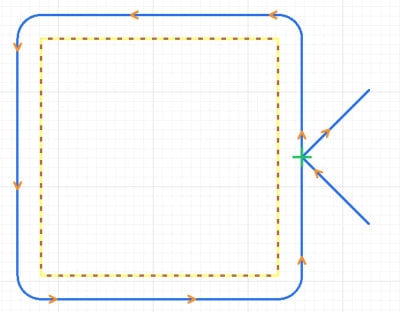
The default lead-out angle is 45°. Adjust length and angle to suit your material and machine clearance. Here is how enabling both a lead-in and lead-out at 45° will appear:
3. Inside vs outside placement
GPath CNC places leads on the side where material is not being kept:
| Profile type | Lead placement |
|---|---|
| Outside, On-line | Approach and depart on the outside of the contour — in free air or waste material 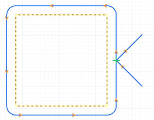 |
| Inside | Approach and depart inside the pocket or hole — staying within the area being cleared 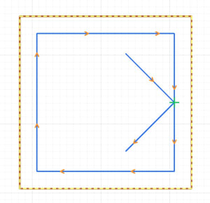 |
If a lead would gouge the part — for example, an inside profile lead in overlapping the toolpath, GPath CNC may shorten, omit, or warn about the lead. Check the toolpath panel after saving if you see a lead adjustment notice.
4. Combining leads with ramping
Leads work alongside Entry Ramping, with one restriction:
- Zig Zag ramping is the recommended setting, the tool can ramp along the lead-in and continue around the profile:
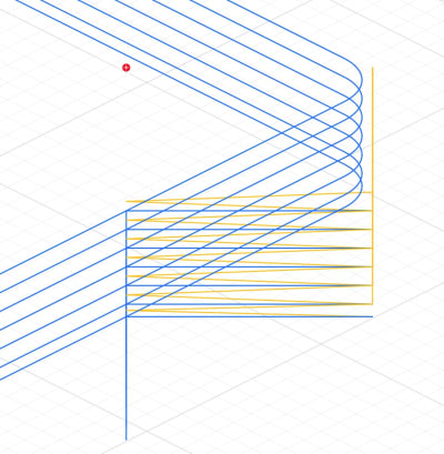
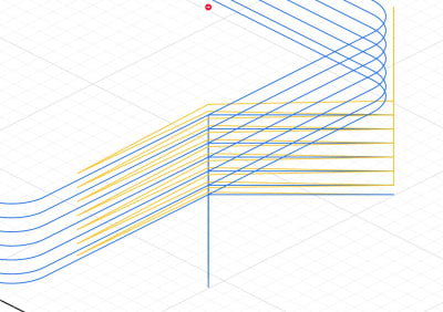
When the ramp distance exceeds the lead length, the tool follows the shapes path while descending:
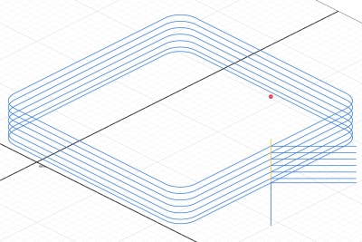
Use Vertical Plunge with leads when you only need the straight approach and a simple vertical drop at the profile start.
5. Start point and depth
Leads attach to the profile start point you choose. You can choose the start point by enabling Select start positions in the Toolpath Simulator tab. Move the start to a straight edge or a corner where a lead fits cleanly.
Each depth pass repeats the lead-in (and lead-out when enabled) at the same geometry, so entry stays consistent through multi-pass cuts.
6. Leads with bridges / tabs
Bridges / Tabs are never placed on lead-in or lead-out moves, only on the cut loop, so approach and exit stay clear of bridges. Tabs near the start position or ramp may also be shifted to avoid conflict with entry.
7. When to skip leads
Leads are not always necessary:
- Inside pockets with plenty of clearance — ramping alone may be enough.
- Roughing passes where entry marks will be removed later.
- Tight geometry where no valid lead fits into the space.
For visible outer contours and final passes on parts where entry quality matters, leads are worth enabling.