GPath CNC
Profile
Last updated Jul 26, 2026, 11:41 AM
1. Create a profile toolpath
Open the Toolpaths tab in the right sidebar and click New Profile Toolpath, or right-click selected shapes on the canvas and choose New profile toolpath from selection….
The toolpath panel opens. Assign a tool from the tool database, add the shapes to cut, set depths, and save the toolpath.
2. Profile type
Profile toolpaths follow a line or drawing on the canvas. The tool can follow on the center line, or offset inside/outside by the tool radius.
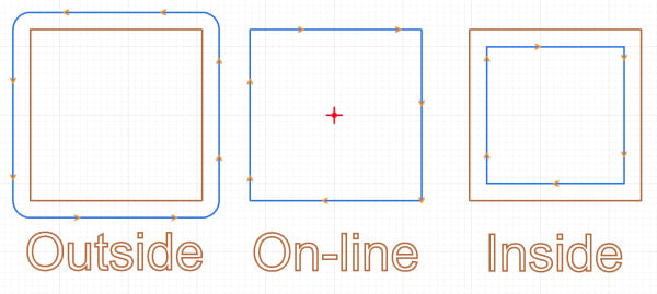
Choose how the cutter relates to the drawn outline:
| Type | Use for |
|---|---|
| Inside | Cut inside the shape — pockets, holes, insets |
| Outside | Cut outside the shape — parts, outer contours |
| On-line | Cut exactly on the drawn path — no offset |
The panel shows a milling-direction diagram for the selected type.
3. Milling direction
| Direction | Typical use |
|---|---|
| Conventional | Tool rotates against the cut direction, often better on older or less rigid machines |
| Climb | Tool rotates with the cut direction, often gives a cleaner finish on rigid setups |
Toggle Sharp corners when you want the tool to stay on the true corner instead of rolling around fillets. This will maintain a sharper point for corners.
Milling direction is indicated by direction arrows on the canvas toolpath preview
4. Start point
Profile toolpaths have the option to modify toolpath start points. This allows choosing where the tool first begins to cut out a shape/vector.
Switch to the Toolpath Simulator central tab. Use Load in the toolbar to load one profile toolpath, or Load all toolpaths to preview every profile operation together.
In the simulator view row (far right), turn on Select start positions.
The toolpaths tab in the right sidebar has an option to toggle Start positions. This will display the start positon marker on the canvas.
5. Depth and tool
Set Start Depth (machine z=0) and Finish Depth in project units. When the finish depth exceeds the tool step-down, GPath splits the cut into multiple Z passes automatically.
Feed rate, plunge rate, spindle speed, and step-down come from the assigned tool.
6. Entry ramping and leads
Profile toolpaths offer two entry options in the panel — Entry ramping and Leads:
| Option | Summary |
|---|---|
| Entry Ramping | How the tool reaches cut depth at the start — vertical plunge, smooth ramp along the path, zig zag, or spiral |
| Leads | Straight angled approach and exit segments before and after the profile cut |
Pockets use ramping only, leads are profile-only. See the dedicated guides for when to use each and how they interact:
7. Bridges/tabs
Bridges/tabs can also be enabled with the profile toolpath. Leaving a short raised strip of material so the part stays attached until you snap or cut them free after machining.
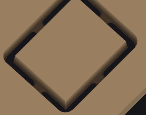
This avoids potential damage as the finished part becomes loose at full depth.
| Option | Summary |
|---|---|
| Auto | Place tabs evenly around each shape (auto), or click them on the canvas(manual) |
| Manual | Click the |
Check our bridges/tabs guide for more information.